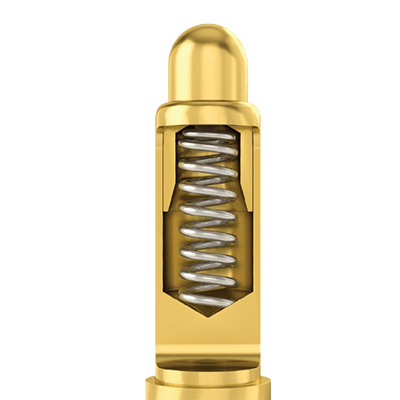
Probe springs are core elastic components for Pogo Pin test probes, precision test fixtures, semiconductor probe cards and high-current connectors, directly determining probe contact stability, service life, signal integrity and current-carrying capacity. Compared with standard off-the-shelf springs, custom probe springs feature miniaturized dimensions, high dimensional precision and excellent working-condition adaptability. Improper design or manufacturing process easily triggers poor contact, pin jamming, fatigue fracture, resistance drift and pin burnout, resulting in test failure, production line shutdown and reduced finished-product yield.
Combining mass-production specifications and actual test data from the precision probe industry, this article comprehensively sorts out core technical specifications, common customization pitfalls, process QC standards and acceptance criteria for custom probe springs. All data cited is factual without inflated figures or vague conclusions, covering customization requirements across semiconductor testing, PCB inspection, consumer electronics verification and high-current conduction applications.
I. Fundamental Core Parameters for Custom Probe Springs (Accurate & Uninflated Data)
Distinct from conventional compression springs, custom probe springs are defined by micron-level dimensional tolerance, controllable spring force, low fatigue degradation, low electrical impedance and compatibility with high-frequency / high-current working environments. Precise parameter matching against actual service conditions is the prerequisite to avoid downstream customization defects. Widely adopted industrial precision standards are listed below:
1. Core Dimensional Specifications (Precision Customization Thresholds)
Most probe springs are miniature compression springs designed for inner probe tubing ranging from 0.15 mm to 3.0 mm, with mainstream precision tolerances complying with established mass-production norms:
- ◎Wire Diameter: Standard range 0.03 mm ~ 0.8 mm; ultra-precision semiconductor grade down to 0.02 mm; production tolerance ±0.005 mm. Fine wire gauges (≤0.1 mm) must be manufactured under constant temperature & humidity (23±2 ℃, 50±5%RH) to eliminate dimensional shift caused by thermal expansion and contraction.
- ◎Outer / Inner Diameter: Tolerance ±0.01 mm, sized to match clearance between spring and probe barrel. Excessive clearance leads to eccentric pin binding; insufficient clearance causes compression seizure and loss of spring rebound.
- ◎Free Length: Tolerance ±0.02 mm, directly defining effective working stroke and preload of probes, a decisive factor for stable contact force.
- ◎Active / Total Coils: Active coil count dominates spring force linearity, normally set between 3~8 coils. High-frequency precision applications demand strict pitch uniformity with pitch error controlled within ±0.005 mm.
-
2. Spring Force Specifications (Core for Working Condition Matching)
Probe contact force is fully governed by spring preload; improper spring force accounts for 80% of all poor-contact failures. Mature industrial application benchmarks:
- ◎General PCB & Consumer Electronics Test: 75~100 gf contact force, capable of penetrating mild pad oxidation while preventing substrate damage.
- ◎Heavy-contamination & High-Current Test: ≥150~200 gf contact force to enhance interfacial adhesion and mitigate overheating & resistance fluctuation under high current.
- ◎Microchip & Thin-wall Solder Joint Test: 30~60 gf contact force to avoid pad collapse and delicate component damage.
- Critical Design Restriction: Total stacking load must be rigorously controlled for multi-probe arrays. A 200-position array with 200 gf per probe yields total closing load up to 40 kg; excessive load deforms fixtures, crushes DUTs and accelerates spring fatigue failure.
-
3. Service Life & Fatigue Specifications
Automated test lines impose stringent fatigue requirements: standard-grade probe springs achieve ≥100,000 compression cycles, premium semiconductor-grade variants ≥500,000 cycles. High-speed reciprocating service requires fatigue-resistant raw materials to prevent load decay and spontaneous fracture.
4. Electrical Compatibility Specifications (Exclusive for HF / High-Current Use)
Key pitfall prevention rule: Probe springs shall never serve as primary current conduction paths. All signal and power currents transmit via plunger and barrel only; springs exclusively provide elastic preload. Current shunting through springs inevitably triggers localized overheating, surface blackening, sharp resistance rise and probe burnout.
II. Top Customization Pitfalls & Practical Solutions
Based on after-sales mass-production failure statistics, nine most frequent customization defects are summarized with actionable countermeasures covering design, material selection, production process and application matching.
Pitfall 1: Blind Spring Force Selection → Poor Contact or DUT Crushing
- ◎Failure Manifestation: Insufficient spring force fails to break through pad oxidation, causing unstable contact resistance and drifting test readings; excessive load collapses micro solder joints and FPC substrates, with permanent spring force degradation occurring after only 30,000~50,000 overload compression cycles.
- ◎Preventive Measure: Specify spring force strictly per application instead of arbitrarily over-sizing preload; perform spring force linearity verification for new custom orders to restrict force deviation within ±5% across full effective stroke.
Pitfall 2: Missing Over-compression Protection → Permanent Spring Deformation
- ◎Failure Manifestation: Working stroke exceeds maximum allowable spring compression, resulting in coil nesting, plastic deformation, lost rebound function and permanent pin seizure.
- ◎Technical Fix: Define rated working stroke and maximum compression limit during design with 10%~15% safety margin; add mechanical limit features in structure design via tolerance stacking to avoid over-travel compression.
Pitfall 3: Improper Material Grade → Accelerated Fatigue, Oxidation & Out-of-spec Impedance
- ◎Common Wrong Practice: Substitute precision alloy with ordinary carbon steel, deploy regular copper alloy for high-frequency use or standard stainless steel for elevated-temperature service, leading to surface rust, spring force drop and signal interference.
-
- Standard Material Selection Guide:
- ◎General Testing: SUS304 / SUS316 stainless steel, superior anti-corrosion and cost-performance for ≤100,000-cycle service.
- ◎High-Frequency & Low-Impedance Application: Beryllium Copper (BeCu), outstanding electrical conductivity, stable elasticity and low contact resistance for signal testing.
- ◎Ultra-High-Fatigue Semiconductor Application: Rhenium-Tungsten / Palladium alloy, high-temperature resistant and fatigue-proof with service life exceeding 500,000 cycles.
Pitfall 4: Substandard Plating → Resistance Drift & Unstable Contact
- ◎Failure Manifestation: Low-cost thin plating, partial plating or no underlayer coating peels off in service, triggering base metal oxidation, spiking contact resistance and excessive signal reflection / attenuation for high-frequency circuits.
- ◎Quality Specification: Precision probe springs adopt nickel underlayer plus gold / rhodium-palladium top plating with uniform pore-free coating thickness; high-frequency probes require impedance-matched plating design to align overall probe impedance with equipment module impedance and minimize signal distortion.
-
Pitfall 5: Out-of-tolerance Dimension → Eccentricity, Pin Binding & Slow Rebound
- ◎Root Cause: Loose tolerance on outer diameter, coil count and pitch causes assembly eccentricity, excessive friction during compression, sluggish rebound and inconsistent test performance.
- ◎Process Control: Micro-springs (wire ≤0.1 mm) require micron-precision coiling machines and constant ambient production; pitch tolerance ±0.005 mm, outer diameter tolerance capped at ±0.01 mm to eliminate dimensional variance.
Pitfall 6: Neglected Load Stacking for Multi-probe Arrays → Batch Defects
- ◎Hidden Risk: Single-probe force meets specification yet cumulative array load overpresses fixtures to warp and bend DUTs; sustained overload shortens spring fatigue life and triggers batch failure.
- ◎Remedy: Calculate total closing load prior to array customization and fine-tune single-probe preload to balance contact reliability and overall compression load.
Pitfall 7: Ignored Thermal Risk for High-Current Design → Spring Burning & Blackening
- ◎Core Design Mistake: Unclear isolation of conductive paths allows current shunting through springs under high-current operation, inducing hot spots, discoloration and fuse-like fracture.
- ◎Mandatory Regulation: All high-current probe constructions route full current via plunger and barrel only; springs are limited to elastic preload without any current shunting. Optimize structural heat dissipation to prevent thermal aging under continuous high-temperature operation.
Pitfall 8: No CAE Simulation & Insufficient Sample Iteration Before Mass Production
- ◎Unregulated Factory Practice: Direct mass production against raw drawings without structural, stress or thermal simulation plus zero prototype revision, leading to inconsistent spring force, insufficient lifespan and abnormal signal performance across batches.
- ◎Standard Workflow: Non-standard customization requires 3~5 rounds of prototype iteration; finite element analysis optimizes stress distribution and cross-section geometry, with pre-production validation on spring force stability, fatigue life and impedance consistency.
-
Pitfall 9: Missing Ambient Adaptation Design → Performance Shift from Temperature & Humidity Variation
- ◎Failure Manifestation: Ordinary springs expand/contract and corrode under alternating high/low temperature or humid environment, shifting preload and deteriorating contact reliability.
- ◎Adaptation Solution: Deploy high-temperature-resistant alloys for extreme thermal environments; upgrade plating protection for corrosive humid conditions to guarantee stable performance across -40 ℃ ~ +125 ℃ operating range.
-
III. Core QC Process Standards (Determining Mass Production Yield)
Approximately 70% of spring performance discrepancies stem from inadequate process control; all core manufacturing procedures must be fully enforced without process shortcut:
- 1.Forming: Precision Coiling Under Constant Temperature & Humidity
Miniature springs are produced in temperature/humidity-controlled workshops to prevent wire deformation from ambient fluctuation, securing micron-level precision on pitch, outer diameter and free length while eliminating coiling eccentricity and uneven coil spacing.
- 2.Heat Treatment: Stress Relieving & Dimension Stabilization
Post-forming stress-relief annealing eliminates residual mechanical stress from coiling, preventing long-term spring force degradation and dimensional distortion and drastically extending fatigue lifespan.
- 3.Surface Finishing: Anti-corrosion & Impedance Stabilization
Complete standardized workflow including degreasing, pickling, base pre-plating and precision top plating to avoid coating peeling, pinholes and oxidation defects; dedicated noble-metal plating for HF applications ensures steady contact resistance and controllable signal loss.
- 4.100% Inspection & Sorting for Parameter Consistency
All finished springs undergo full inspection on free length, spring force, outer dimension and appearance, sorted by specification ranges to restrict batch spring force tolerance within ±5% and avoid mass on-site test failure.
-
IV. Application-Based Custom Material & Force Selection Chart
|
Application Scenario |
Specified Spring Force |
Recommended Material |
Core Custom Requirements |
| Standard PCB Functional Test |
75–100 gf |
SUS304 Stainless Steel |
Precise dimension, smooth rebound, basic anti-rust |
| Microchip / Precision Solder Test |
30–60 gf |
Beryllium Copper Alloy |
Low preload, high linearity, no substrate crushing |
| High-Current Conduction Test |
≥150–200 gf |
High-Elasticity Stainless Steel |
Zero current shunting, high contact load, stable heat dissipation |
| HF / Wi-Fi6 Signal Test |
75–100 gf |
BeCu + Precious Metal Plating |
Impedance matching, low signal attenuation, stable resistance |
| High-Life Semiconductor Probe Card |
50–120 gf |
Re-W / Palladium Alloy |
≥500,000-cycle service, ultra-stable, minimal fatigue decay |
V. Finished Product Acceptance Standards (Direct On-site Inspection Checklist)
Five key acceptance criteria for incoming custom springs to block defective lots from production setup:
- 1.Dimensional Accuracy: Free length, outer diameter and wire diameter within drawing tolerance; no eccentricity, physical deformation or irregular coil spacing.
- 2.Mechanical Performance: Excellent spring force linearity across full working stroke with deviation ≤±5%; no binding or delayed rebound.
- 3.Appearance & Plating: Smooth burr-free surface, no oxidation spots, uniform intact plating free of peeling or pinholes.
- 4.Fatigue Reliability: Random sample compression test for 100,000 cycles with post-test spring force decay ≤8%, no deformation or breakage.
- 5.Electrical Property: Constant contact resistance without drift, compliant signal attenuation for HF applications, no thermal overheating caused by spring current shunting.
-
VI. Conclusion: Core Logic to Avoid Customization Failures
Successful custom probe spring design goes beyond pure dimensional conformance to drawings; it requires full-spectrum matching of working-condition parameters, material formulation, structural compatibility and QC acceptance. 90% of customization failures originate from three root causes: arbitrary parameter selection, cutting corners on manufacturing processes and ignoring actual service environment characteristics.
Core Customization Principle: Prioritize impedance for high-frequency projects, conductive path layout for high-current designs, precise preload tuning for micro-precision applications, batch consistency for mass production and material/process optimization for long-life requirements. Strictly control four fatal failure modes: over-compression, abnormal spring force, unintended current shunting and out-of-spec tolerance to eliminate most field test defects at source.

 Tiktok

 Kwai

 REDnote


